Developmental Iterations
The primary goal while designing the quadcopter frame was to minimize the distance between the propellers and fit the plate within that gap. Multiple design iterations were explored due to changes in overall weight and, consequently, propeller size.
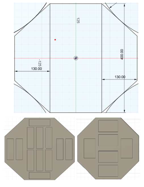
First Iteration:
- The frame’s diagonal dimensions were limited by the propeller size. To maximize the usable area within this constraint, a circular shape would have been ideal. However, we initially considered an octagonal frame.
- The frame extended up to the edges of the propellers, assuming the propellers and the plate exist on separate planes.
We also explored different battery placements on the plate during this phase.
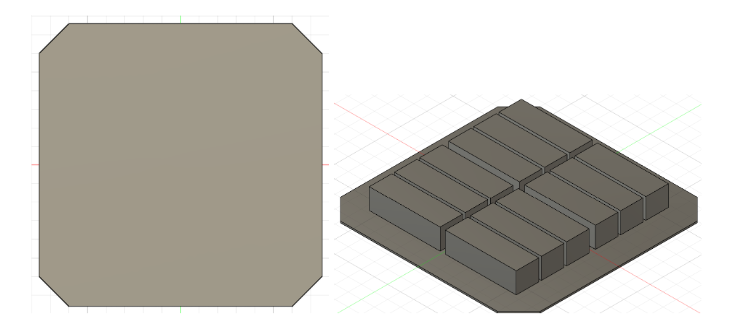
Intermediate Iterations:
As we shifted to 24” propellers, later iterations focused on square plates. When maximizing area within a constrained distance between opposite edges, square or rectangular shapes proved more suitable.
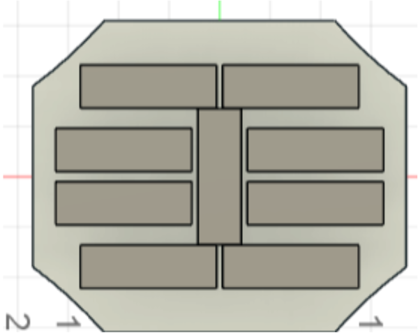
All the electronics required have been arranged on another plate above the battery plate. List of electronics present in this model are:
- Here 3 (Top)
- Pixhawk Cube Orange and Carrier (Center)
- Rocket M5 (Right)
- ESLR RP1 V2 (That small thing)
- RFD 900X (Bottom)
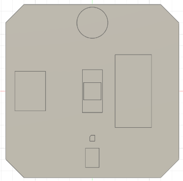
- JetsonNano (Left)
- Electronics were kept on the top plate.
Further Developments:
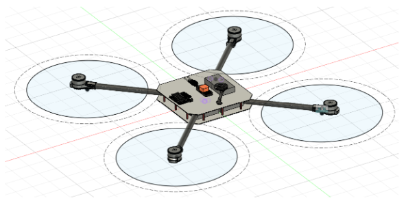
- With changing battery requirements and total weight, we reconsidered the design for 30” propellers with 1.2× clearance. Again, while a circular frame would optimize area, a square shape with rounded corners was chosen—practical and easier to implement. The frame extended up to the propeller edges, assuming separate planes for the frame and propellers.
- After discussions with senior scholars and professors, we finalized a rectangular plate of size 50 × 25 cm, meeting both spatial and efficiency constraints. Batteries were moved to the top plate for quicker setup before the mission.

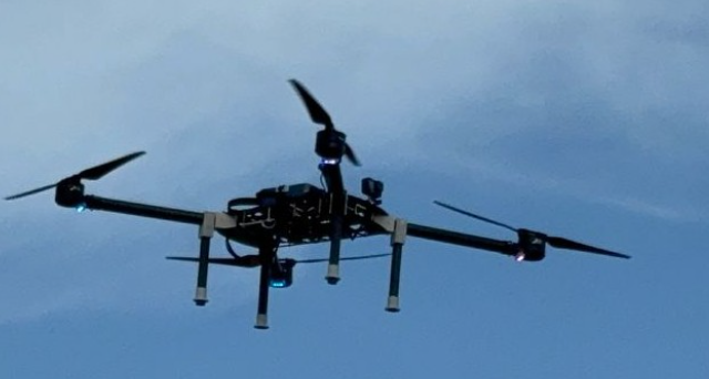
Landing Gear:
We initially planned for slanting landing gear. However, based on advice and considering the large plate size, we opted for vertical landing gear, with joints mounted directly on the boom, just after the boom joints. This approach offered better optimization and simplicity.
The final fabricated design reflects this configuration.